I have trouble with my Tight Spot interfering with the Fall away arrow rest if I dont off set it a bit. I had cut a piece of kyvex but i like that idea better(and the kyvex isnt thick enough )View attachment 422544
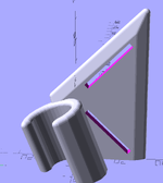
Printed a spacer for my new (to me) Tight Spot 7 Arrow quiver. Normally the sight mount is the the spacer, but I'm utilizing the Bridge-Lock system for dovetails on my Mathews V3x.
The spacer is thinner, lighter, and wider than the sight mount and the extra width reduces the quiver flex a little since it fully supports the back of the QD mount.
Navigation
Install the app
How to install the app on iOS
Follow along with the video below to see how to install our site as a web app on your home screen.
Note: This feature may not be available in some browsers.
More options
Style variation
You are using an out of date browser. It may not display this or other websites correctly.
You should upgrade or use an alternative browser.
You should upgrade or use an alternative browser.
Fun with 3D Printers
- Thread starter philintheblank
- Start date
- Banned
- #82
Nightstandx
FNG
- Joined
- Sep 18, 2023
- Messages
- 69
grate job, have had this in my to do list for a while procrastination have been getting the better of me lately..Recently bought a used QIDI X-Pro 3D printer and have been messing around with TinkerCAD.
Decided to revamp my trekking pole tripod adapter and made up a mount for my outdoorsman bino adapter along with a quick switch plate and lens cover for compact spotter
Also made a window mount for smaller optics (no 4lb spotters allowed on my windows)
Everything was printed with PETG so it should last for a long time and be fine with outside / rainy conditions.
Random low-complexity on-demand stuff is where I find the most value. I wouldn't know how to search for this bauble on a site that sells hardware. Throwing together a parametric cad file doesn't take that long and can be used into the future. Settings are for 2.2mm dyneema (throw line).
.scad file:


.scad file:
JavaScript:
// hook designed to hook knots on small diameter cord and be as snagless as possible

// closed hole diameter
cdLoop = 3.1;
// hook slot width
cdHook = 2;
// slot section od
bigD = 20;
// closed hole section od
smallD = 9;
// slot angle
degSlot = 40;
// thickness
thick = 5;
// minkowski sphere radius, fillet rad sort of
filletRad = 2;
// sets side bulge. adds strength and beauty. low value will cause failed print. tested at 0.4
bulbousness = 0.4;
// 40+ faces for print but it makes minkowski very slow in editing
$fn = 45;

// diff for slicing off top bottom and loop hole
difference(){
  //trace sphere for chamfering around union of two cylinders with slot
  minkowski(){
    //two cylinders with a slot cut at around ? degrees
    difference(){
        union(){
          cylinder(d = bigD, thick * bulbousness, center = true);
          // center starts origin, so translate up sin30 and right cos30
          translate([cos(degSlot) * bigD/2, sin(degSlot) * bigD/2, 0]){
              cylinder(d = smallD, thick * bulbousness, center = true);
            }
          }
        // slot:
        translate([50, 0, 0]){
            cube([100, cdHook + 2 * filletRad, 2], center = true);
          }
        // rounded slot pocket:
        cylinder(d = cdHook + 2 * filletRad, 2, center = true);
      } // diff

    sphere(r = filletRad);

    }

    // minus:
  translate([cos(degSlot) *  bigD/2, sin(degSlot) * bigD/2, 0]){
      cylinder(d = cdLoop, 55, center = true);
    }
  for (dir = [-1, 1]) translate([0, 0, dir * (thick / 2 + 1)]){
      cube([99, 99, 2], center = true);
    }
}RubiconJoey
FNG
- Joined
- Sep 9, 2024
- Messages
- 37
Love this thread. I've been printing odd and end things for a long time. Just recently printed some chassis weights. Printed them hollow and filled the with lead shot. A pair of them is 8 ounces.

RubiconJoey
FNG
- Joined
- Sep 9, 2024
- Messages
- 37
Just printed these barrel vice blocks to use in a bench vise. They slipped using a business card at around 30ft-lbs, but once I switched to the heat shrink tubbing I was able to torque the action to 80ft-lbs no problem.

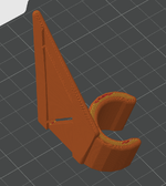
I always liked side-of-head lights like that old maglite strap, forgot the name. But the angle was bad -- the strap is too low on the forehead or too high in back.
Figure I'll try printing a pre-angled clip for 20mm strap.
Figure I'll try printing a pre-angled clip for 20mm strap.
C-like:
// Headlamp bracket to mount lamp to nylon strap v1
// requires tweaking of plateScale when changing strap width
// v2 TODO:
//     autoscale plate geometry with strapwidth, light cant
//     headcurve is janky

// downward light angle
lCant = 20;
// clipin angle
clipRot = -30;
// clip length:
clipLength = 29;
// light diametewr
lDiam = 22;
// clip tightness, use 0.8 (tight) to 0.99 (no retention)
clippiness = 0.85;

// plate thick
plateThick = 7;
// plate scale - how many times cliplength, affected by strap and cant
// 2.7 seems right for 25mm strap, 1.9 for 20mm strap
plateScale = 2.2;

// strap width
strapWide = 21;
// strap thickness try 3mm
strapThick = 2.5;

// head curve, puts slight curve in head side
hcRad = 550;
hcDepth = 4.2;

minkRad = 2;
$fn = 20;
// mechanical interface facets should be high when printing
interfaceFacets = 35;

// lop off several things, each gets comment
difference(){

minkowski(){
  // union of plate and clip
  union(){
    //clip
    // translate so back hits yz plane
    translate([ (1.2 * lDiam / 2), 0, 0]){
      // rotate for cant
      rotate([lCant, 0, 0]){
        // rotate clip entry
        rotate([0, 0, clipRot]){
          color("Green"){
            difference(){
                // outer clip diameter account mink
                cylinder(d = 1.2 * lDiam, 2 * clipLength, center = true);

                // minus light diam account mink
                cylinder(d = lDiam + minkRad, 99, center = true, $fn = interfaceFacets);
                // minus clip entry account mink, the cube y dimension coefficient is clip clippiness, try 0.8-0.95
                translate([44, 0, 0]){
                    cube([88, clippiness * (lDiam + minkRad), 99], center = true);
                  }
              } // end diff
            }
          } // rot clip
        } // rot cant
      } // trans in xy

      // begin plate:
      rotate([0, -90, 0]){
          linear_extrude(plateThick - minkRad - plateThick / 2, scale = 1.15){
              // this polygon adjusts to cant angle and clip length
              polygon([ [0, 0], [clipLength * cos(lCant), -1 * clipLength * sin(lCant)], [plateScale * clipLength, strapWide + 7] , [0, strapWide + 7] ]);
            }
        }


    } // un

// this does the fillets
sphere(r = minkRad);

}

// cut off below xy plane
translate([0, 0, -22]){
    cube([99, 99, 44], center = true);
  }
// cut off back of plate slot for strap
translate([-44 - minkRad, strapWide / 2 + 5, 0]){
    cube([88, strapWide, 222], center = true);
  }
// add top slot
translate([-40, strapWide / 2 + 5, (plateScale + 1) / 1.8 * clipLength * cos(lCant)]){
    rotate([45, 0, 0]){
        cube([88, 1.414 * strapWide, strapThick], center = true);
      }
  }
// add bottom slot
translate([-40, strapWide / 2 + 5, strapWide * 1.414 / 2]){
    rotate([-45, 0, 0]){
        cube([88, 1.414 * strapWide, strapThick], center = true);
      }
  }
// head curve
translate([-1 * hcRad - plateThick + hcDepth, 0, (strapWide * 1.414 / 2 + (plateScale + 1) / 1.8 * clipLength * cos(lCant)) / 2 ]){
    rotate([90, 0, 0]){
        cylinder(r = hcRad, 99, center = true, $fn = 300);
      }
  }


} // plane diff
Attachments
I'm accustomed to making diagonal features that traverse the Z axis in CAD when target is FFF print, but my old printer is pretty terrible at this. Decided to try a horizontal slot with a 20mm flat suspended overhang on my new printer. Pretty brutal feature for filament. Results are tolerable though. Losing a couple strands on cleanup is easier than dealing with supports.
This was a case where print could not be re-oriented because maximum bending strength in needed in the clip.
This was a case where print could not be re-oriented because maximum bending strength in needed in the clip.
Attachments
This is sweeeeet. Anyone want to print me oneGot inspiration from the range finder clip thread that was recently posted here
Rangefinder holder
I used a CB radio microphone hanger and button (The round thing that mounts to the CB mic) to make the perfect rangefinder holder that I mounted to my bino harness. This allows me to mount the rangefinder up high minimizing arm movement and keeping it away from other gear. I also never have to...www.rokslide.com
So I printed the holder and a backer plate so I could attach with some 2M cap screws.
Used some random bolts and washers to make the tab and some good quality 2 sided tape to attached to my rangefinder.
Works pretty slick, thanks again to the OP for posting about their sweet setup.
")
OP
OP
philintheblank
FNG
It's not as daunting of a task once you dive into it. Start with small projects, build as you go and don't be afraid of failure. Some prints take many iterations before you are satisfied with the outcome.I cannot fathom having the ability to see an issue and go print something to fix it.
You would also be surprised how many free plans are uploaded to the 3D printing libraries that can be useful for hunting. Lots of times I have had an idea and there is already a finished project online that can be used for free
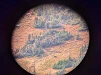
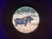
I printed a spotting scope adapter for my Pixel 7 with a Magsafe case on my Bambu A1 Mini: Printables Link
You'll need to measure your specific phone if it's an Android, or use Apple's dimensions that are somewhere in that link. Also need to buy some magnets that are like $4 a piece. Got some pretty good pictures. The moose were less than 150 yards and the best was 1+ mile away and 1k+ feet up. It took a few iterations, but I'm happy with the product. I ran out of black PLA when I was printing, hence the blue hue on the outside. Next iteration will be with black PETG I think. With the magnet embedded it's as simple as placing the adapter on the spotting scope and placing your phone on the adapter, the magnet holds the phone on it.
You'll need to measure your specific phone if it's an Android, or use Apple's dimensions that are somewhere in that link. Also need to buy some magnets that are like $4 a piece. Got some pretty good pictures. The moose were less than 150 yards and the best was 1+ mile away and 1k+ feet up. It took a few iterations, but I'm happy with the product. I ran out of black PLA when I was printing, hence the blue hue on the outside. Next iteration will be with black PETG I think. With the magnet embedded it's as simple as placing the adapter on the spotting scope and placing your phone on the adapter, the magnet holds the phone on it.
Attachments
i know of thinkaverse what are some others? most of what i see on thinkaverse are pretty cheesyIt's not as daunting of a task once you dive into it. Start with small projects, build as you go and don't be afraid of failure. Some prints take many iterations before you are satisfied with the outcome.
You would also be surprised how many free plans are uploaded to the 3D printing libraries that can be useful for hunting. Lots of times I have had an idea and there is already a finished project online that can be used for free
Also, one keyword to look out for is "parametric".
Parametric is why I've been gravitating more towards OpenSCAD over traditional CAD like solidworks.
Traditional CAD still usually has limited parametric functionality, and I've seen 3d print sites that allow configuration and render of these.
Parametric meaning that it lets you simply input a couple important dimensions, then adjusts the model to fit those dimensions and spits out a printable file. It opens up a lot more than static models even if you don't draft.
BBob
WKR
Nite-Ize? We used those for a number of years.that old maglite strap, forgot the name
Yep that one. The only two problems was that it would flop under weight, and that unless you pulled it down to your eyebrows, it would point up into the sky when walking. This was the final print of my version. It looks dorky in use, but I'm satisfied.Nite-Ize? We used those for a number of years.

C-like:
// Headlamp bracket to mount lamp to nylon strap v3
// mostly tested with 21mm light and 20mm strap
// requires tweaking of plateScale when changing strap width
// TODO:
//     autoscale plate geometry with strapwidth, light cant
//
//  PRINT: +1 base, +1 perimeter, 50% infill, random seam, slot overhangs barely work

// downward light angle
lCant = 25;
// clipin angle
clipRot = -30;
// clip length:
clipLength = 29;
// light diameter, testing at 0.1 over measured
lDiam = 21.1;
// clip tightness, use 0.8 (tight) to 0.99 (no retention)
clippiness = 0.88;

// plate thick
plateThick = 9;
// plate scale - how many times cliplength, affected by strap and cant
// 2.7 seems right for 25mm strap, 1.9 for 20mm strap
plateScale = 1.45;

// strap width, rec 0.5mm under
strapWide = 19.5;
// strap thickness try 2mm
strapThick = 1.9;

// head curve, puts slight curve in head side
hcRad = 175;
hcDepth = 5.5;

minkRad = 2;
$fn = 20;
// mechanical interface facets should be high when printing
interfaceFacets = 35;

// lop off several things, each gets comment
difference(){

minkowski(){

      // begin plate:
      rotate([0, -90, 0]){
          linear_extrude(plateThick - minkRad - plateThick / 2, scale = 1.15){
              // this polygon adjusts to cant angle and clip length
              polygon([ [0, 0],
              [clipLength * cos(lCant), -1 * clipLength * sin(lCant)],
              [plateScale * clipLength - 3, strapWide + 4],
              [plateScale * clipLength - 3, strapWide + 8],
              [0, strapWide + 7] ]);
            }
        }

// this does the fillets
sphere(r = minkRad);
}

// cut off below xy plane
translate([0, 0, -22]){
    cube([99, 99, 44], center = true);
  }
// cut off back of plate channel for strap
translate([-44 - minkRad, strapWide / 2 + 8, 0]){
    cube([88, strapWide, 222], center = true);
  }
// add top slot
translate([-2, strapWide / 2 + 8, (plateScale + 1) / 1.825 * clipLength * cos(lCant)]){
    rotate([0, 45, 0]){
        cube([16, strapWide, strapThick], center = true);
      }
  }
// add bottom slot
translate([-2, strapWide / 2 + 8, strapWide / 4]){
    rotate([0, -45, 0]){
        cube([16, strapWide, strapThick], center = true);
      }
  }
// head curve
translate([-1 * hcRad - plateThick + hcDepth, 0, (strapWide / 2 + (plateScale + 1) / 1.95 * clipLength * cos(lCant)) / 2 ]){
    rotate([90, 0, 0]){
        cylinder(r = hcRad, 99, center = true, $fn = 300);
      }
  }

} // plane diff

// add little lower bump
difference(){
  minkowski(){
      translate([ (1.2 * lDiam / 2 - 2.5), -8, 0]){
        // rotate for cant
        rotate([lCant, 0, 0]){
          // rotate clip entry
          rotate([0, 0, clipRot]){
            color("Green"){
              difference(){
                  // outer clip diameter account mink
                  cylinder(d = 1.2 * lDiam, 2 * clipLength, center = true);

                  // minus light diam account mink
                  cylinder(d = lDiam + minkRad, 99, center = true, $fn = interfaceFacets);
                  // minus clip entry account mink, the cube y dimension coefficient is clip clippiness, try 0.8-0.95
                  translate([44, 0, 0]){
                      cube([88, clippiness * (lDiam + minkRad), 99], center = true);
                    }
                } // end diff
              }
            } // rot clip
          } // rot cant
        } // trans in xy

      sphere(r = minkRad);
    }
    // cut off below xy plane again?
    translate([0, 0, -22]){
        cube([99, 99, 44], center = true);
      }
}That is cool!Lyman primer catcher. The factory one blocked the hole and did not fit very well
HuntOregon
FNG
- Joined
- Oct 24, 2024
- Messages
- 17
You seem pretty knowledgeable. Is there a service where you design the part, but a company will print it for you? I figure might be cheaper than buying a printer for just a few prints?I use TinkerCAD. It's free and pretty basic so easy to learn. I am starting to outgrow it with some more complex designs I have in mind, but it was a great tool to start with. It has a few tutorials and how-to's
There are a lot of companies that will do that. Just Google 3d print service. Never used once since I have a printer but here is the first that came up for me.You seem pretty knowledgeable. Is there a service where you design the part, but a company will print it for you? I figure might be cheaper than buying a printer for just a few prints?

Manufacturing on Demand
From prototyping to production, our network of over 10,000 suppliers has the capacity for all of your manufacturing projects.
www.xometry.com
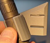
I struggle getting the range finder back into a pouch quietly and quickly so made a hard case felt lined with elastic pull tab retention. Made with PETG and worked great but an improvement would be to make it with TPU to quiet it down a bit more. Putting the range finder in and out is noiseless but buckles and branches tend to hit it and tap.
![20241103_094127[1].jpg](https://forumdata.rokslide.com/file/forumdata/data/attachments/758/758987-e368935fa599bd693df80ae6afcbb7c1.jpg?hash=42iTX6WZvW "20241103_094127[1].jpg")
![20241103_094116[1].jpg](https://forumdata.rokslide.com/file/forumdata/data/attachments/758/758988-ebc01ba54df17a3a837353c87b6261d6.jpg?hash=68AbpU3xej "20241103_094116[1].jpg")
![20241103_094203[1].jpg](https://forumdata.rokslide.com/file/forumdata/data/attachments/758/758989-abfc829c89ebafb124c51d7622a58f03.jpg?hash=q_yCnInrr7 "20241103_094203[1].jpg")
Similar threads
- Replies
- 0
- Views
- 288
- Replies
- 9
- Views
- 733
- Locked
- Replies
- 5
- Views
- 492
- Replies
- 0
- Views
- 44

Featured Video
Latest Articles
- Kifaru Enters the Hunting Apparel Space: Review
- From Big Bucks to Bear Hunts: Catching Up with Jordan Budd
- Mule Deer Days Wildlife Conservation Mashup
- A Hidden Gem: Hunting Washington with Kari Thomas
- Prime Divide Bow Review
- Knowledge From Storms: Surviving and Thriving in the Backcountry with John Barklow
- DIY Wyoming Pronghorn Hunt
- Unlock Precision Shooting: Master Your Hunting Game with Competitive Insights
- Topo Topper Rincon Review
- Tony Trietch on Big Mule Deer, Desert Bulls & Western Hunting Evolution