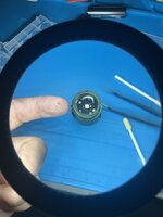
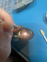
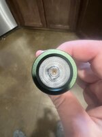
I started repairing some electronics around my house because all the tools fit in a small drawer and its quiet enough that I can do it inside after the kids go to bed. I also am pretty into flashlights, so i got some cheap alibaba soldering supplies to fix a few broken headlamps and flashlights. A lot of my cheaper lights function really well but dont render colors accurately, have a weird tint shift, or I just dont like the LED color. So I have started swapping the LEDs.
The Sofirn D25/H25 has become the Rokslide special of headlamps so I figured Id share my swap on this one. These come with a LH351HD 5000k. I will try not to nerd out too hard here. Its not a bad LED at all, there is a slight green shift in the ones I have and they have a low R9 which means they render reds poorly. The Nichia 519A has the same output, has no tint shift, and a better R9. The 4500k is my preferred color in the 519s, it just looks perfectly neutral to me, no blue, no yellow.
Just wanted to share this, I know its a little different. Hopefully it helps someone revive an old light, or make a favorite light a little better. Most dont know this is an option and a nice LED is just a few dollars. There are also some people who do this on the side and its very cheap if you dont want to tackle it on your own.
1. Take the front cover off the light by removing the 4 x 2mm hex screws.
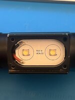
2. Add a little flux to the wire pads, I set my iron to 750F and use a little 60/40 solder to melt the lead free solder the factory uses.
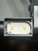
3. Gently pry the board out and wipe all the old thermal paste off with some alcohol
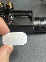
4. You dont have to, but I take a soldering wick and remove some of the old solder and clean up with board with some alcohol and a q tip before I swap the LEDs
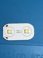
5. Put the board on a hot plate, the factory solder can be hard to melt sometimes, I had my plate set abnormally high at 230C. After it sits on the hot plate for a few seconds you can take some tweezers and pick the LEDs off very easily.
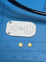
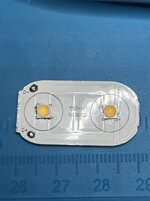
6. I normally clean the board again once it cools at this step, these boards have a mark for the positive side of the LED, but you can check continuity of the LED pad to the wire leads at this step if it doesnt. You also need to know the positive and negative of the LED, on a 519 the negative side is marked by a tiny triangle, but i still check with a SMD tester. you then place it on the pad so that + is + and - is -. It doesnt have to be perfect, they will suck in centered when you put it back on the hot plate. I use a very tiny bit of solder paste under the new LEDs, thats the grey smudge in the image, but you dont have to have it.
7. Back on the plate, you can actually see the LED pop into place as the solder melts on the hot plate.
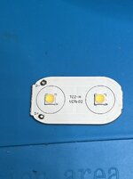
8. Again I clean it up, check the wire connection points to make sure they work.
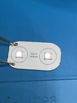
9. I add some arctic silver thermal paste in a very very thin layer to the back and pop the board back in the light at this point
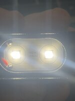
10. I add some flux to the tips of the wires and soldering pads and re attach the positive and negative leads to the board and shes ready to re assemble and use. The centering rings around the LEDs need to be reused, dont lose those.
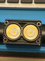
The Sofirn D25/H25 has become the Rokslide special of headlamps so I figured Id share my swap on this one. These come with a LH351HD 5000k. I will try not to nerd out too hard here. Its not a bad LED at all, there is a slight green shift in the ones I have and they have a low R9 which means they render reds poorly. The Nichia 519A has the same output, has no tint shift, and a better R9. The 4500k is my preferred color in the 519s, it just looks perfectly neutral to me, no blue, no yellow.
Just wanted to share this, I know its a little different. Hopefully it helps someone revive an old light, or make a favorite light a little better. Most dont know this is an option and a nice LED is just a few dollars. There are also some people who do this on the side and its very cheap if you dont want to tackle it on your own.
1. Take the front cover off the light by removing the 4 x 2mm hex screws.

2. Add a little flux to the wire pads, I set my iron to 750F and use a little 60/40 solder to melt the lead free solder the factory uses.

3. Gently pry the board out and wipe all the old thermal paste off with some alcohol

4. You dont have to, but I take a soldering wick and remove some of the old solder and clean up with board with some alcohol and a q tip before I swap the LEDs

5. Put the board on a hot plate, the factory solder can be hard to melt sometimes, I had my plate set abnormally high at 230C. After it sits on the hot plate for a few seconds you can take some tweezers and pick the LEDs off very easily.

6. I normally clean the board again once it cools at this step, these boards have a mark for the positive side of the LED, but you can check continuity of the LED pad to the wire leads at this step if it doesnt. You also need to know the positive and negative of the LED, on a 519 the negative side is marked by a tiny triangle, but i still check with a SMD tester. you then place it on the pad so that + is + and - is -. It doesnt have to be perfect, they will suck in centered when you put it back on the hot plate. I use a very tiny bit of solder paste under the new LEDs, thats the grey smudge in the image, but you dont have to have it.

7. Back on the plate, you can actually see the LED pop into place as the solder melts on the hot plate.

8. Again I clean it up, check the wire connection points to make sure they work.

9. I add some arctic silver thermal paste in a very very thin layer to the back and pop the board back in the light at this point
10. I add some flux to the tips of the wires and soldering pads and re attach the positive and negative leads to the board and shes ready to re assemble and use. The centering rings around the LEDs need to be reused, dont lose those.


