I've been getting several DM's about my auto dispenser, so I figured I'd do a write up on it with a material list.
I was looking for an auto dispenser a while back and everyone that I saw had some sort of issue with it or it was way too expensive. As an engineer, I like building things so figured I'd tackle this one.
The dispenser works off time. There is a control board that has settings in which you can control time. In that case the board also has a COM, NC (normally closed), NO (normally open). This board allows you to control 1 single motor with the help of a simple voltage regulator. The second board in the picture is for controlling the slow speed and kill power portion of the wiring. I'll explain as we go along.
This is the ultimate goal. A dispenser that holds over 1 lb of powder, needs no warmup time, and will dispense powder in a pretty fast setting so you're not waiting. The one difference with this rather than the digital "all-in-one" RCBC, Honady, etc, is that the digital units have an approach to weight feature. It allows the motor to spin up to a certain weight settings then start slowing down. This is not like that. If you overshoot your weight, take off time. If you under shoot weight, add time. Once you get close, the beam will trigger the optical sensor and kill power.


Material list:
Here is a list of everything that I used. I already had some switches but they can be bought anywhere for cheap. I
12v Relay Module
AEDIKO 4pcs DC 12V Relay Module 1 Channel Relay Board with Optocoupler Isolation Support High or Low Level: Amazon.com: Industrial & Scientific
Junction Box
Timer Relay
Amazon.com: UCTRONICS DC 12V Programmable Time Delay Relay Module with Metal Enclosure, On Delay and Off Delay Timer for Automobile, Raspberry Pi, Industrial Control, and Other Automatic Control Projects : Automotive
Speed Controller
https://www.amazon.com/RioRand-RR-P...B00N30UK2M&psc=1&ref_=pd_bap_d_grid_rp_0_46_t
Clear Hopper
Motor 350rpms and mount
350 RPM Premium Planetary Gear Motor - ServoCity®
 www.servocity.com
Brass Tube
4mm to 5/16 Coupling
 www.servocity.com
NPN slotted sensor EE-SX 676PWR

www.ebay.com
2” to ½” reducer (the kind that tapers like a funnel
Switches ( I had these already, but very cheap) on/off main power switch, on/off cycle switch, the white button is a Mom on / off push button switch. It is used to bump or trickle.


I was looking for an auto dispenser a while back and everyone that I saw had some sort of issue with it or it was way too expensive. As an engineer, I like building things so figured I'd tackle this one.
The dispenser works off time. There is a control board that has settings in which you can control time. In that case the board also has a COM, NC (normally closed), NO (normally open). This board allows you to control 1 single motor with the help of a simple voltage regulator. The second board in the picture is for controlling the slow speed and kill power portion of the wiring. I'll explain as we go along.
This is the ultimate goal. A dispenser that holds over 1 lb of powder, needs no warmup time, and will dispense powder in a pretty fast setting so you're not waiting. The one difference with this rather than the digital "all-in-one" RCBC, Honady, etc, is that the digital units have an approach to weight feature. It allows the motor to spin up to a certain weight settings then start slowing down. This is not like that. If you overshoot your weight, take off time. If you under shoot weight, add time. Once you get close, the beam will trigger the optical sensor and kill power.
Material list:
Here is a list of everything that I used. I already had some switches but they can be bought anywhere for cheap. I
12v Relay Module
AEDIKO 4pcs DC 12V Relay Module 1 Channel Relay Board with Optocoupler Isolation Support High or Low Level: Amazon.com: Industrial & Scientific
Junction Box
Timer Relay
Amazon.com: UCTRONICS DC 12V Programmable Time Delay Relay Module with Metal Enclosure, On Delay and Off Delay Timer for Automobile, Raspberry Pi, Industrial Control, and Other Automatic Control Projects : Automotive
Speed Controller
https://www.amazon.com/RioRand-RR-P...B00N30UK2M&psc=1&ref_=pd_bap_d_grid_rp_0_46_t
Clear Hopper
Motor 350rpms and mount
350 RPM Premium Planetary Gear Motor - ServoCity®
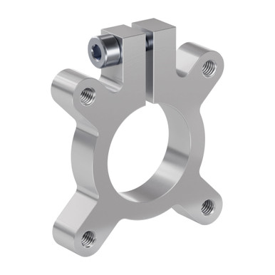
1302 Series Clamping Hub (22mm Bore)
Welcome to ServoCity where you can get the parts you need to bring your ideas to life! From servos to switches, from actuators to Actobotics, we work hard to bring you the best components backed by unparalleled technical support
www.servocity.com
Brass Tube
Amazon.com: K&S Precision Metals Round Brass Tube 8133 – 5/16" OD x 0.014" Wall x 12" Long – DIY Crafts, Plumbing, HVAC, Modeling, Made in USA, 1 Tube : Arts, Crafts & Sewing
Amazon.com: K&S Precision Metals Round Brass Tube 8133 – 5/16" OD x 0.014" Wall x 12" Long – DIY Crafts, Plumbing, HVAC, Modeling, Made in USA, 1 Tube : Arts, Crafts & Sewing
www.amazon.com
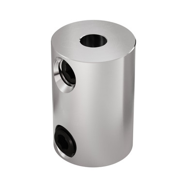
4mm to 5/16 Coupling
0.3125" to 4mm Set-Screw Shaft Coupler
Welcome to ServoCity where you can get the parts you need to bring your ideas to life! From servos to switches, from actuators to Actobotics, we work hard to bring you the best components backed by unparalleled technical support
www.servocity.com
NPN slotted sensor EE-SX 676PWR
5-24VDC NPN/PNP Slotted Optical Switch Photoelectric Sensor With 1 Meter Cable | eBay
Slotted Optical Switch 5MM Photoelectric sensor DC5~24V 100mA. EE-SX670-WR NPN Light Up when Power on. EE-SX671-WR NPN Light Up when Power on. EE-SX672-WR NPN Light Up when Power on. EE-SX673-WR NPN Light Up when Power on.www.ebay.com
2” to ½” reducer (the kind that tapers like a funnel
Switches ( I had these already, but very cheap) on/off main power switch, on/off cycle switch, the white button is a Mom on / off push button switch. It is used to bump or trickle.